Background
I recently got my hands on a TRS-80 Model 1, but it didn’t come with a power supply. I figured not a big deal, I should be able to build one. However the more I looked in to the power supply and the available replacements, the more bewildered I got about this mysterious power supply. This article dives into the details of the power supply. I’ll cover a building a replacement supply in a separate article.
The Various Models
There are at least seven variants of the TRS-80 Model 1 power supply. Below is a table of them.
| Market | US | US | Europe | Europe | Europe | Japan | Australia |
| Mfg. Loc. | USA | Taiwan | UK | Taiwan | Taiwan | Japan | Australia |
| Input Voltage | 120V 60Hz 50W | 120V 60Hz 50W | 220~240V 50Hz | 240V 50Hz 50VA | 220~240V 50Hz 50VA | 100V 50~60Hz 32VA | 240V 50Hz |
| Output | 17.0V AC 1A 19.8VDC .35A | 17.0VAC 1A 19.8VDC .35A | 21.2VAC 1A 17.6VDC .35A | 21.2VAC 1A 17.6VDC .35A | 21.2VAC 1A 17.6VDC .35A | 19.2VAC 1A 16.2VDC .35A | 15VAC 1.4A 20VDC .35A |
| Catalog # | 4000004 | 4000007 | 26-9100 | 26-9100 | 26-9100 | 26-9100 | 26-9100 |
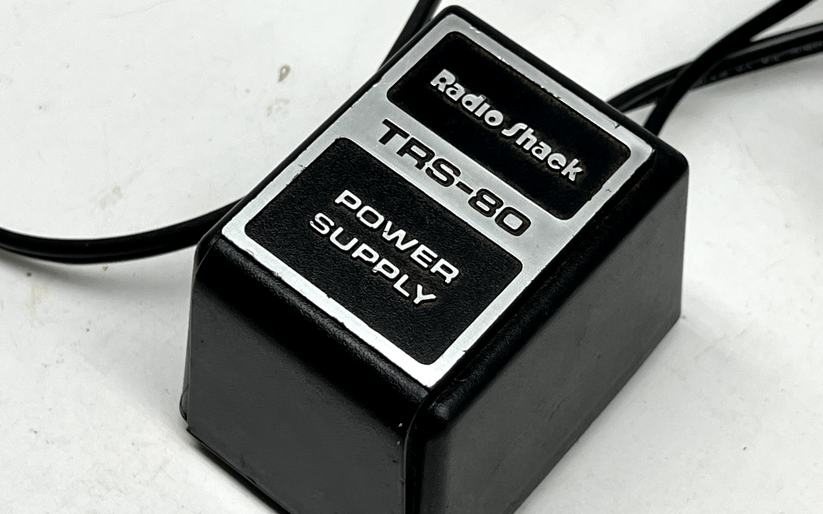
| Top Photo | 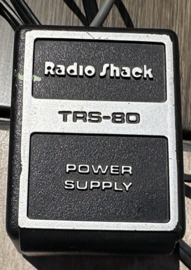 | 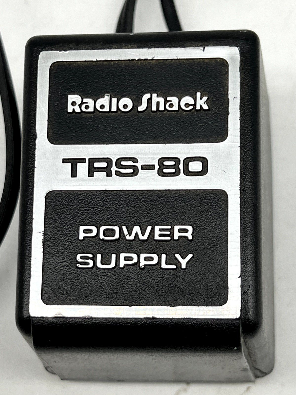 | 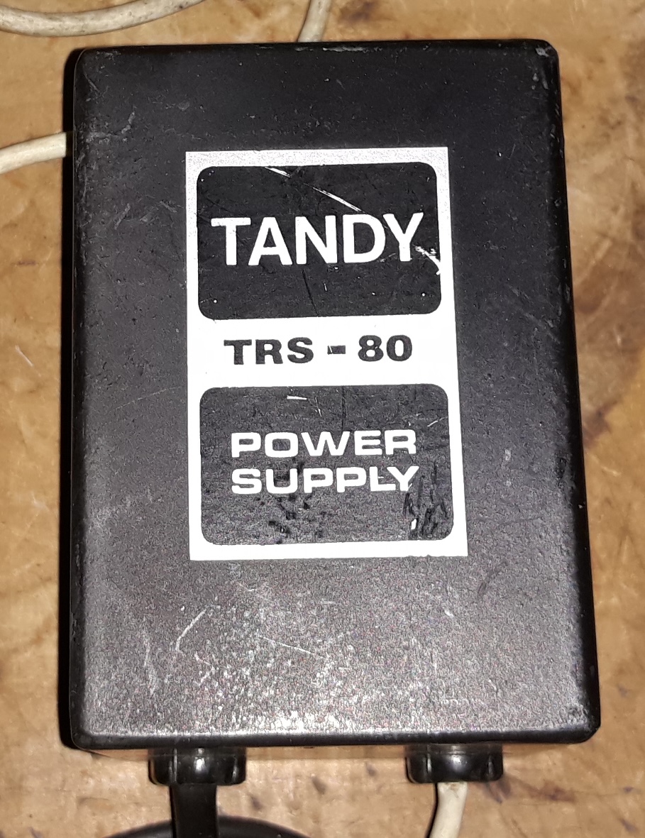 | 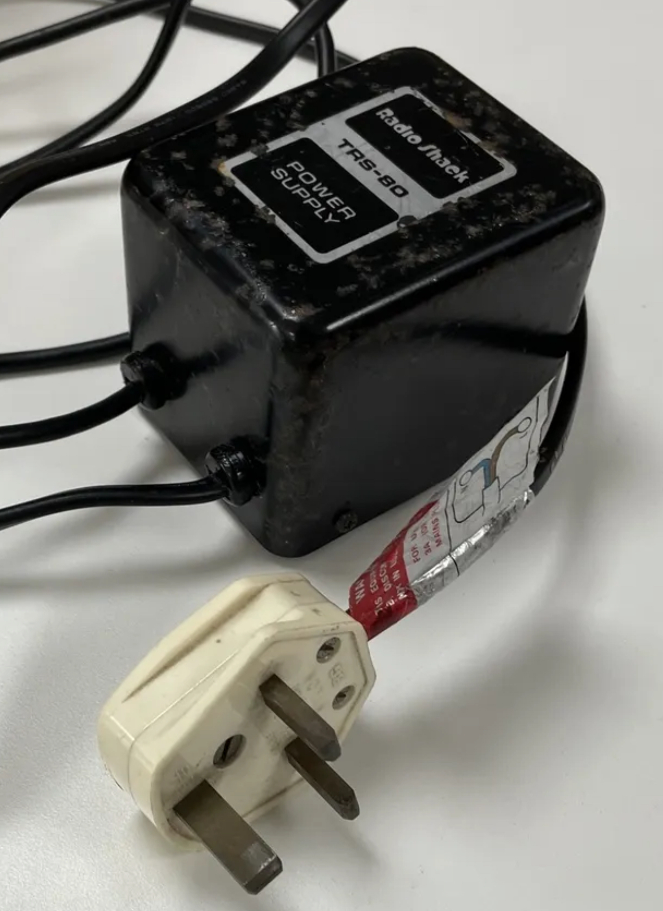 | 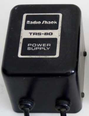 | 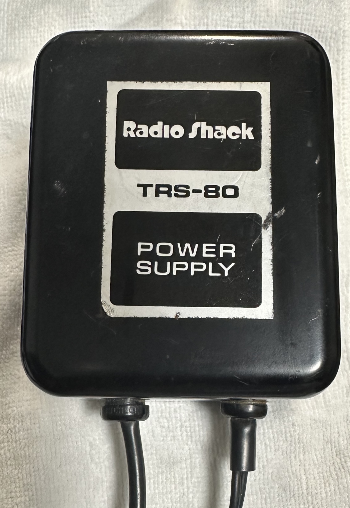 | 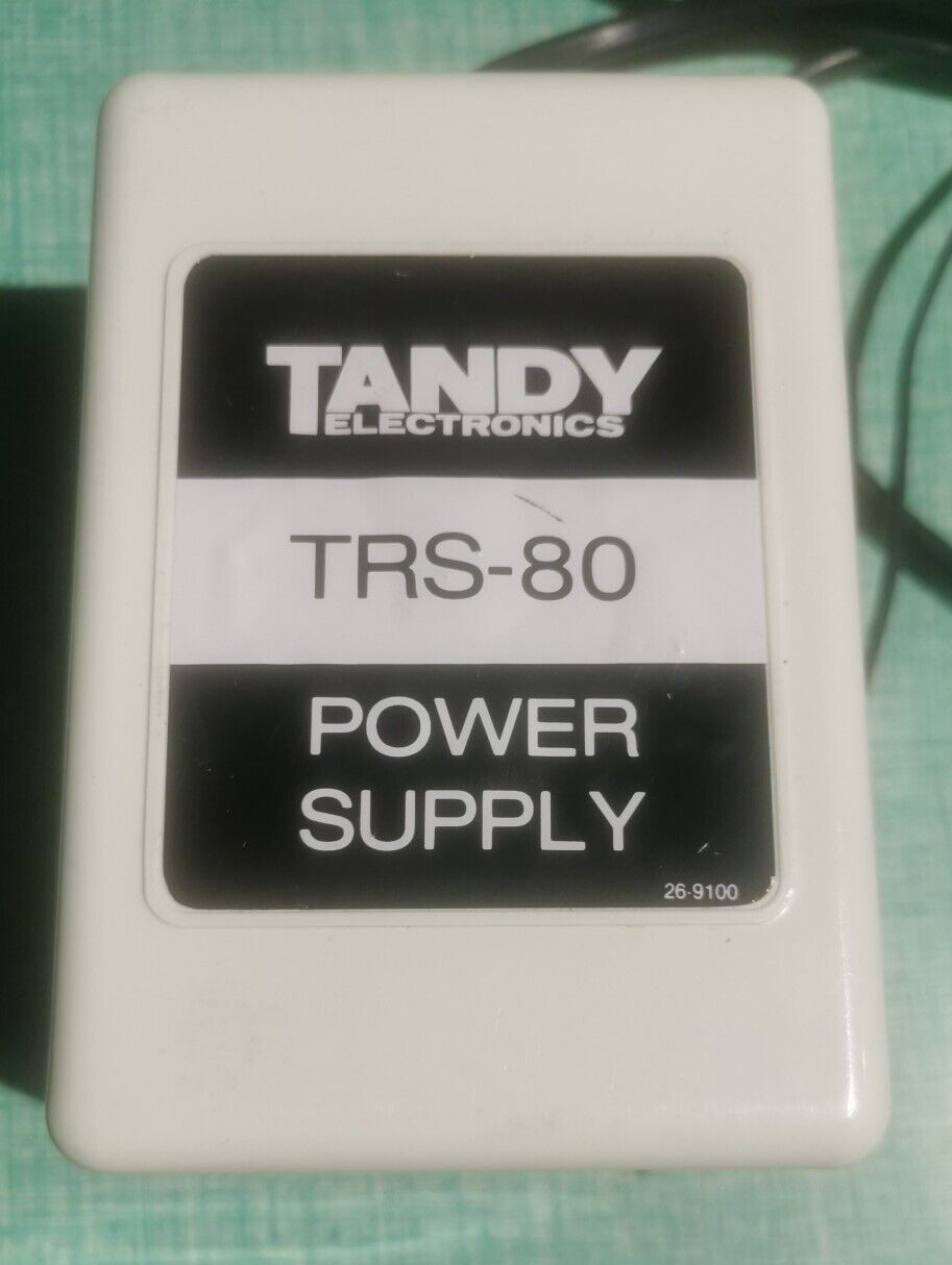 |
| Bottom Photo | 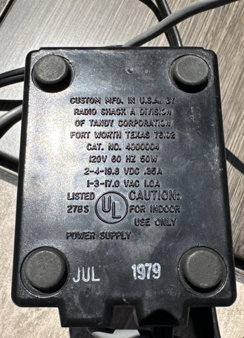 | 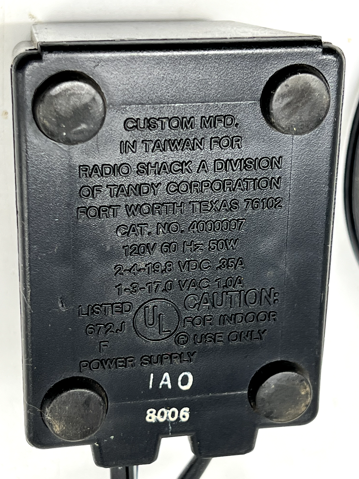 | 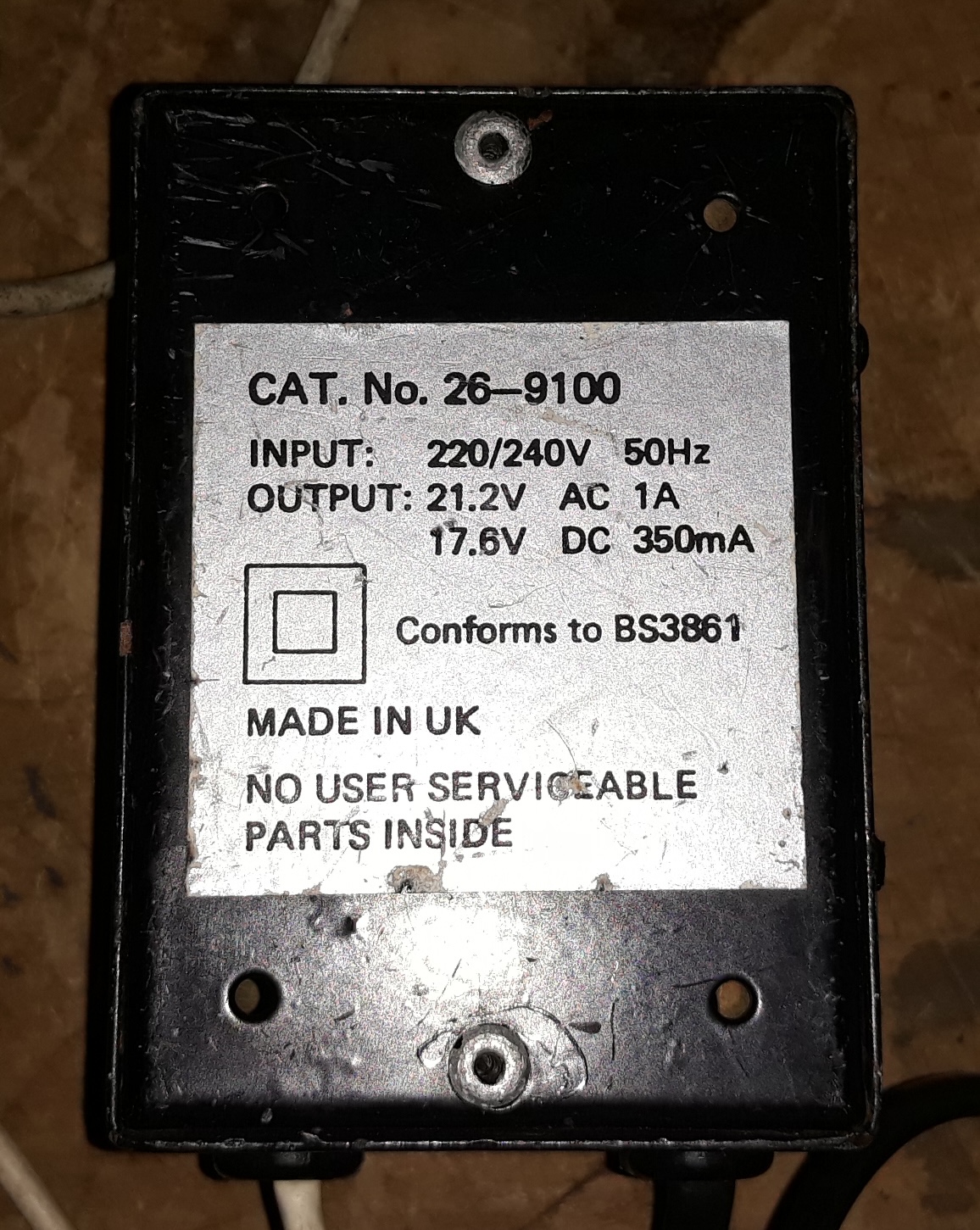 | 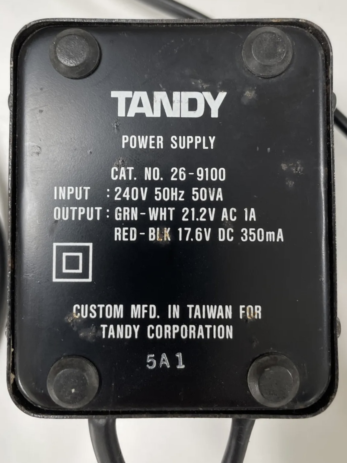 | 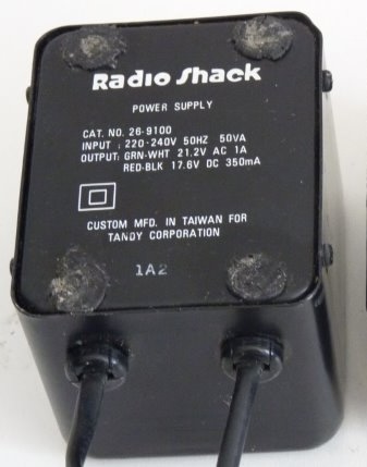 | 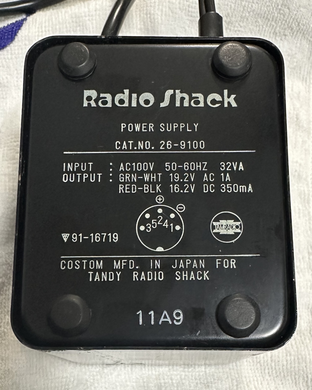 | 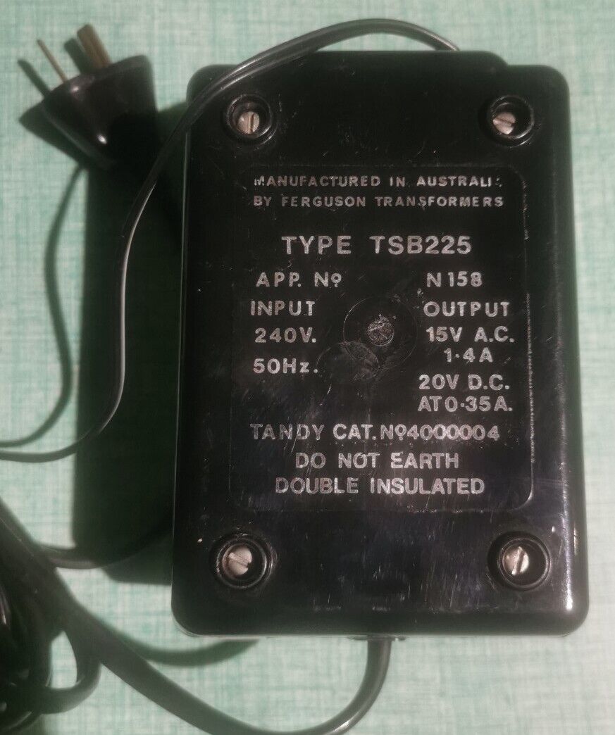 |
The Insides
The insides of the power supply can be easily accessed by removing the 4 screws on the bottom. However, the model 4000004 can not be opened in a non-destructive way. The best way to get inside it is to use a Dremel to remove the base plate, which is not recommanded.
First let’s talk about just the transformer. It has one primary winding and two center-tapped secondary windings.
The AC output is achieved by attaching the two secondary taps in series. Then the two center taps are used to output the 17v AC.
The two outer taps are taken though diodes to be rectified. The output of the two diodes combined generates the 19.8v DC when referenced to where the two taps are joined.
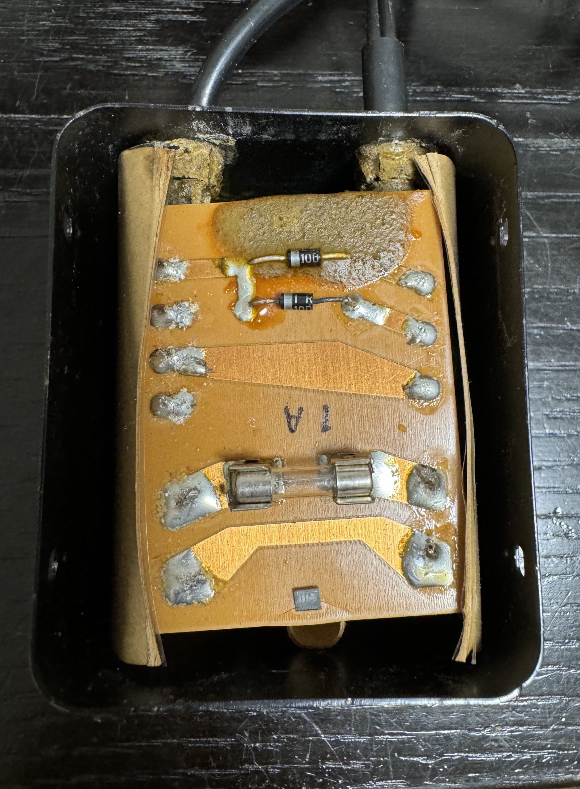
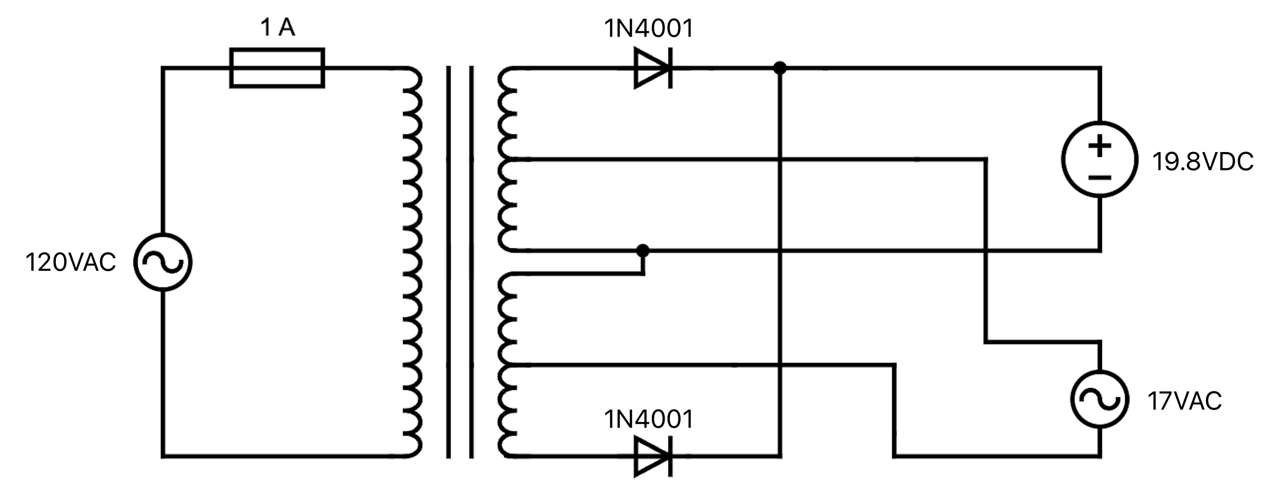
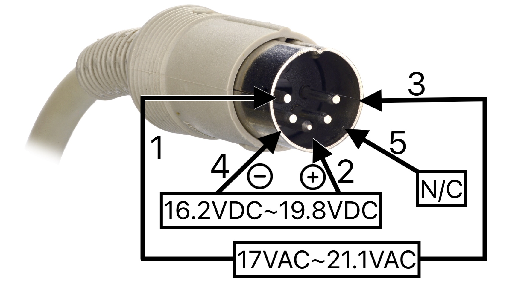
There is also a 1 amp fuse inside the power supply brick in case there are any shorts. Below is the output voltage. It will vary depending on which region and model of the power supply you have.
Design Notes
The DC output on the power supply is not smoothed by any capacitors, this occurs inside the TRS-80 system.
Connecting two center-taps is not a typical design. By doing this it ensures that the AC output is not causing any interference on the DC output.
The power supply runs at 0.2A/6W/20VA on idle. Once connected to a powered on TRS-80, the power supply starts pulling 0.28A/14W/29VA.
The DC output is used to generate the 12v rail. The DC goes straight to a voltage regulator on the TRS-80 to lower it down to the desired 12v.
The AC output goes through a half-wave rectifier on the TRS-80. The +5v is generated using a voltage regulator, while the -5v is obtained via a zener diode.
Using this information, we can proceed with building our own replacement transformer.
Leave a Reply